
Technical Specifications
| Parameter | Specification |
|---|---|
| Nominal Diameter | 0.8–50 mm |
| Diameter Tolerance | m6 / h8 / h11 |
| End Design | Arc-Shaped Ends / Chamfered Ends / Flat Ends |
| Length | According to product drawings and specifications |
| Length Tolerance (m6) | +0.3/0, +0.5/0, +0.8/0, depending on length |
| Length Tolerance (h8 / h11) | +0.5/0, +1.0/0, +1.5/0, depending on length |
| Material | According to DIN EN ISO 683-4 or DIN 1652 |
| Surface Roughness | Rz 4 / Rz 16 / Rz 63, depending on surface area and tolerance type |
| Surface Treatment | Electroplating, Phosphating, or other agreed treatments |
| Edge Condition | All edges rounded or deburred |
| Customization | Dimensions, materials, tolerances, surface treatments, and packaging according to agreed requirements |
Locating Accuracy & Fit Selection
Interference Fit for Secure Positioning: The m6 tolerance provides a positive diameter allowance, making it suitable for designed interference-fit applications where the pin needs to be pressed into a mating hole.
Close Dimensional Fit: The h8 tolerance offers a narrower dimensional tolerance range than h11, making it suitable for applications requiring closer control of pin diameter.
General Fit Requirements: The h11 tolerance provides a wider diameter tolerance range for assemblies with less demanding diameter control requirements.
Mating Hole Compatibility: The hole diameter and tolerance must be considered together with the pin dimensions. Proper fit selection helps prevent excessive insertion force, unwanted looseness, and positioning deviations.
Pin End Design & Tolerance Classes
DIN 7 Parallel Pins are available in different end designs and diameter tolerance classes to meet various mechanical assembly requirements. The end geometry and dimensional tolerances influence pin insertion, hole fit, and component positioning. Selecting the correct configuration helps ensure compatibility with the mating components.
| Tolerance Class | End Design | Diameter Range | Main Characteristics |
|---|---|---|---|
| m6 | Arc-Shaped Ends | 1–50 mm | Positive diameter tolerance for applications requiring a tighter interference or press fit |
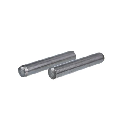
| h8 | Chamfered Ends | 0.8–50 mm | Close dimensional tolerance with chamfered edges to facilitate pin insertion |
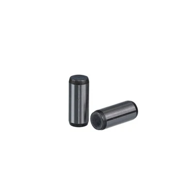
| h11 | Flat Ends Without Chamfer | 0.8–50 mm | Wider diameter tolerance for applications with less demanding dimensional fit requirements |
End Design Considerations:
- Arc-Shaped Ends: Rounded ends help guide the pin into the mating hole and reduce the risk of edge interference during installation.
- Chamfered Ends: Chamfers provide an insertion lead-in, helping align the pin with the hole during assembly.
- Flat Ends: A straight end profile provides a simple cylindrical pin configuration for applications where chamfered or rounded ends are not required.
- Tolerance Selection: The appropriate tolerance class should be determined by the required fit, hole dimensions, and assembly method.

Material & Finish Selection Considerations:
- Material Compatibility: Select the steel grade according to mechanical requirements, machining or manufacturing specifications, and the operating environment.
- Surface Roughness Control: The cylindrical surface finish should correspond to the selected tolerance class to support the intended mating fit.
- Corrosion Protection: Electroplating or phosphating can be specified when additional surface protection is required. The treatment should be compatible with the material and dimensional requirements.
- Customized Requirements: Special material grades and alternative surface treatments can be reviewed according to customer drawings and technical specifications.
Anhui Pins supports customized DIN 7 parallel pin requirements for machinery manufacturers, OEM buyers, and industrial fastener distributors. From dimensional specifications to material and surface finish selection, product requirements can be reviewed according to customer drawings and assembly conditions.
- Customized Dimensions: Specify pin diameters, lengths, and dimensional requirements according to your mechanical assembly drawings.
- Tolerance Class Selection: Choose m6, h8, or h11 diameter tolerance classes based on the required fit and positioning requirements.
- Material & Surface Finish: Discuss suitable steel materials, stainless steel options where applicable, electroplating, phosphating, and other agreed surface treatments.
- Drawing-Based Production: Submit technical drawings or product specifications for evaluation, quotation, and order confirmation.

DIN 7 Parallel Pin Manufacturer

As an industrial fastener manufacturer and supplier, Anhui Pins supports B2B customers sourcing precision parallel pins for machinery, tooling, and equipment assemblies. We focus on specification-based product supply to help customers match pin dimensions and tolerances with their application requirements.
- Standard-Based Production: DIN 7 parallel pins are supplied with reference to applicable dimensional specifications, including diameter tolerances, end configurations, and length requirements.
- Dimensional Accuracy Control: Product specifications cover pin diameter, length, end geometry, and surface finish to support compatibility with mating components.
- Flexible Order Support: We work with OEM manufacturers, wholesale buyers, and fastener distributors on standard specifications, customized requirements, and bulk purchasing.
- Specification Confirmation: Technical drawings, material requirements, tolerance classes, and packaging details can be reviewed before order confirmation to reduce specification mismatches.
FAQ
What is the main purpose of a parallel pin in a mechanical assembly?
A parallel pin is primarily used to locate and align two or more components. It helps maintain their relative positions during assembly and operation. Unlike bolts and screws, its main function is positioning rather than providing clamping force.
Are DIN 7 parallel pins solid or hollow?
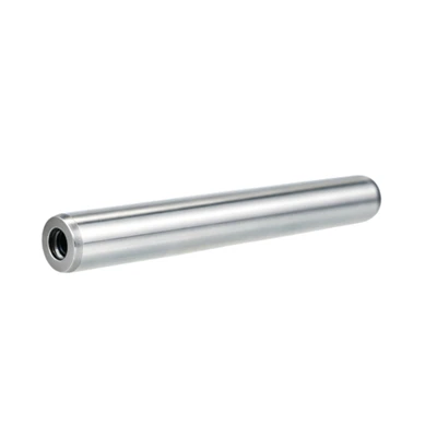
DIN 7 parallel pins have a solid cylindrical body. They do not feature the longitudinal slot found in slotted spring pins or the internal extraction thread found in DIN 7979 pins. This solid construction makes them suitable for applications requiring rigid component positioning.
What is the difference between a parallel pin and a slotted spring pin?
A parallel pin has a solid cylindrical structure and relies on the specified dimensional fit with the mating hole. A slotted spring pin has an elastic structure that compresses during installation and generates radial force against the hole wall. The selection depends on the assembly design, positioning requirements, and expected operating conditions.
Can parallel pins be used as pivot pins?
They can be incorporated into certain pivot-related assemblies, provided the design accommodates the expected movement and loading. However, a standard locating pin should not automatically be treated as a rotating shaft or bearing component. Applications involving continuous rotation require additional consideration of wear, lubrication, and contact conditions.
Should I use one or two parallel pins to align two components?
One pin can establish a positioning reference, while two pins spaced apart are commonly used to control both relative position and orientation between mating components. Their spacing and hole locations should be accurately designed to avoid assembly interference or excessive constraint.
What tools are commonly used to install parallel pins?
A suitable arbor press, assembly press, or pin installation tool can be used depending on the pin size and fit. The mating holes should be properly prepared and aligned before insertion. Using an appropriate tool helps prevent damage to the pin ends and surrounding components.
Can parallel pins be reused after disassembly?
Parallel pins may be reused when they remain undamaged and still meet the required dimensional and fit conditions. However, repeated removal and installation can cause wear to the pin or mating hole. For precision locating assemblies, replacing worn pins is recommended to maintain positioning accuracy.
Hot Tags: din 7 parallel pins, China din 7 parallel pins manufacturers, suppliers, factory, iso 2338 pin, precision ground dowel pins, small metal dowel pins, spring dowel pin, ss dowel, Zylinderstifte Mit Innengewinde