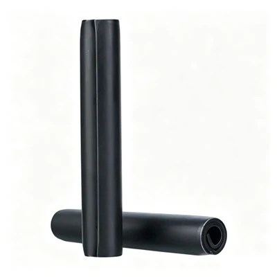

Steel Compression Limiter Technical Specifications
| Parameter | Specification |
|---|---|
| Product Name | Steel Compression Limiter |
| Available Series | AY / BY / CY / DY |
| Material | Carbon Steel |
| Installation Method | Press-In |
| Compatible Bolt Grade | 8.8 / 10.9 |
| Nominal Thread Sizes | M4 – M12, Depending on Series |
| AY Series | M4 – M12 / Standard Type |
| BY Series | M4 – M10 / Precision Type |
| CY Series | M6 – M8 / Heavy-Duty Type |
| DY Series | M5 – M10 / Oval Type |
| Design Features | Radial Tension / Oval Structure According to Series |
| Surface Treatment | Zinc-Nickel Alloy Coating / Other Specified Treatments |
| Customization | Custom Dimensions, Materials, Coatings & Installation Requirements |
Core Functions & System Role
Steel compression limiter is installed inside plastic or composite mounting holes to control bolt tightening force by transferring clamping load through the steel sleeve instead of the plastic body. This structure maintains joint geometry under assembly torque and prevents deformation during long-term fastening conditions.
- Protects plastic components from compression damage during bolt tightening
- Transfers preload load path from plastic → steel sleeve → bolt head/nut interface
- Maintains joint stability under repeated tightening and vibration conditions
- Supports assembly systems using ISO 8.8 / 10.9 grade bolts
Mechanical Performance Benefits
The steel sleeve carries the axial bolt preload directly through its cylindrical wall, reducing long-term plastic creep and stress relaxation in polymer housing materials under sustained tightening conditions.
The fixed-length structure defines a controlled clamping distance between mating parts, maintaining consistent joint thickness in bolted assemblies during repeated tightening cycles and service life use.
Excess tightening torque is transferred through the steel body instead of the plastic substrate, preventing local deformation or cracking around the mounting hole under assembly load conditions.
The rigid sleeve geometry provides a stable load reference inside the joint, allowing minor misalignment between mating plastic components to be absorbed without uneven stress distribution.

Installation Methods & Assembly Compatibility
Press-in installation is applied after machining, where the steel compression limiter is inserted into the plastic or composite hole using manual or pneumatic press equipment to ensure full seating inside the bore.
Mold-in installation is used during injection molding, where the limiter is placed in the mold cavity so that molten plastic flows around the sleeve and locks it in position after cooling.
The structure is compatible with automated assembly systems, allowing consistent insertion force control in high-volume production lines for plastic housing or structural panel assemblies.
Controlled length tolerance ensures the limiter defines a fixed compression stop inside the joint, keeping bolt tightening distance consistent and preventing over-compression of surrounding plastic material.

Manufacturing Process & Quality Control
Steel Compression Limiters are manufactured through controlled forming and finishing processes to maintain consistent sleeve geometry, wall thickness, and length for stable assembly performance.
- Stamping & Forming
Steel strip or tubing is formed into the specified cylindrical profile, with control of the sleeve diameter, wall thickness, and overall geometry.
- Heat Treatment
For applicable grades and load requirements, heat treatment is used to obtain the specified mechanical properties and dimensional stability.
- Precision Sizing & Grinding
After forming and heat treatment, critical dimensions are corrected or finished to meet the specified inner diameter, outer diameter, length, and dimensional tolerances.
- Surface Treatment
Parts receive the specified protective coating, such as zinc or zinc-nickel plating, according to the required corrosion protection and application environment.
- Dimensional & Functional Inspection
Finished limiters are checked for ID, OD, length, wall thickness, roundness, surface condition, and load-bearing performance. Inspection results are controlled by batch to maintain consistency for repeat production.
FAQ
What engineering problem does a steel compression limiter solve?
It prevents plastic deformation in bolted joints by taking the axial tightening load through a steel sleeve instead of allowing the force to directly compress plastic housing material.
How does it work inside a plastic assembly?
The limiter is installed inside a through-hole, and when the bolt is tightened, the clamping force is transferred from the bolt head into the steel sleeve, creating a rigid load path between fastened components.
What materials are typically used and why?
High carbon steel or low carbon steel is used to provide sufficient compressive strength and dimensional stability under repeated bolt tightening cycles and long-term static load conditions.
What is the difference between press-in and mold-in installation?
Press-in is used after plastic parts are formed, while mold-in places the limiter into the injection mold so it becomes permanently embedded during the molding process.
Hot Tags: steel compression limiter, China steel compression limiter manufacturers, suppliers, factory, compression limiters, cylindrical compression limiter, Steel Compression Limiter