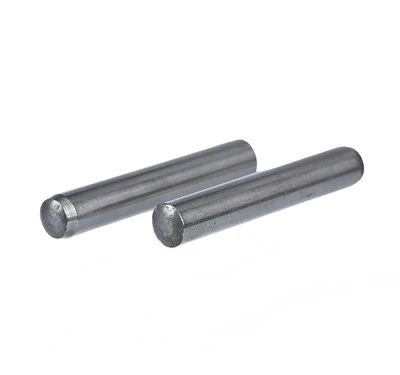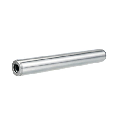
In precision mechanical assemblies, dowel pins are used to align components, maintain repeatable positioning, and prevent unwanted movement between mating parts. However, selecting the correct nominal diameter is only one part of the process. The dimensional tolerance of the pin and the finished size of the mating hole determine how the components fit together.
For equipment manufacturers and industrial parts buyers, an incorrect fit can lead to difficult installation, loose positioning, damaged holes, or problems during maintenance. Understanding dowel pin tolerances and hole fit requirements helps engineers specify suitable dimensions before production and helps purchasing teams avoid ordering parts that do not match the assembly design.

Why Do Dowel Pin Tolerances Matter in Mechanical Assemblies?
Dowel pin tolerances define the permitted variation in the pin's actual diameter. Even when two pins share the same nominal diameter, their measured dimensions may differ within the specified tolerance range.
These dimensional differences directly affect assembly conditions:
- Positioning accuracy: Excessive clearance between the pin and hole can allow unwanted movement between components.
- Assembly consistency: Controlled dimensional tolerances help maintain consistent installation conditions across production batches.
- Joint stability: An appropriate interference fit helps retain the pin in its designated position.
- Maintenance requirements: The selected fit influences whether a pin can be removed and replaced without damaging surrounding components.
For manufacturers producing machinery, molds, fixtures, and precision equipment, pin and hole tolerances should be reviewed together at the design stage.
What Do Dowel Pin Tolerances Actually Mean?
Dowel pin dimensional tolerances describe the acceptable variation from a specified nominal diameter. They are commonly expressed through tolerance grades or tolerance zones, depending on the applicable standard.
The main dimensional terms include:
| Term | Meaning |
|---|---|
| Nominal Diameter | The specified reference diameter of the pin |
| Actual Diameter | The measured diameter of the manufactured pin |
| Upper Deviation | The maximum permitted dimensional deviation |
| Lower Deviation | The minimum permitted dimensional deviation |
| Tolerance Range | The difference between the maximum and minimum permitted dimensions |
For example, a dowel pin specified with a nominal diameter of 10 mm does not necessarily measure exactly 10.000 mm. Its acceptable dimensional range depends on the specified tolerance class.
Common ISO shaft tolerance designations include h6 and m6. These zone limits define different dimensional boundaries and govern the resulting fit when paired with a mating hole tolerance. Standard dowel pins under ISO 2338 carry predefined tolerance classes; buyers should confirm whether to follow the standard default tolerance or apply a custom tolerance before releasing drawings.
When ordering dowel pins, buyers should confirm both the nominal diameter and the required tolerance class rather than specifying diameter alone.
How Does Hole Size Affect Dowel Pin Fit?
A dowel pin's dimensional tolerance cannot determine the final assembly fit independently. The diameter and tolerance of the mating hole are equally important.
The actual relationship between the pin diameter and hole diameter determines whether the assembly has clearance, transition, or interference.
Three dimensions should be considered:
- Hole nominal diameter: The reference size specified in the engineering drawing.
- Hole tolerance: The permitted variation in the finished hole diameter.
- Finished hole size: The actual measured diameter after machining.
For precision assemblies requiring tight dimensional control and consistent surface finish, holes are machined by drilling followed by reaming. Reaming removes stock uniformly to narrow the hole tolerance band and reduces surface roughness on the hole wall.
Engineers should calculate the possible fit window using the maximum and minimum dimensions of both the pin and hole. This calculation verifies that all produced parts will stay within the intended fit range.
Choosing Between Clearance, Transition, and Interference Fits
The appropriate fit depends on how the dowel pin functions within the assembly. Different fit types provide different levels of retention, positioning, and removability.
| Fit Type | Main Characteristics | Typical Application Requirements |
|---|---|---|
| Clearance Fit | The hole is larger than the pin | Easy insertion, removal, and adjustment |
| Transition Fit | Tolerance bands of pin and hole overlap; individual parts may produce slight clearance or interference | Controlled positioning with manageable assembly force |
| Interference Fit | The pin's maximum diameter exceeds the hole's minimum diameter | Secure permanent retention in a fixed position |
Clearance Fit
A clearance fit provides space between the pin and hole, allowing easier installation and removal. It may be suitable for assemblies requiring frequent disassembly, provided the permitted movement does not compromise positioning requirements.
Transition Fit
A transition fit arises from overlapping tolerance zones between the pin and hole. Randomly paired parts may land in slight clearance or slight interference. It is selected when positioning accuracy and moderate assembly force are both required.
Interference Fit
An interference fit occurs when the pin diameter exceeds the hole diameter. Installation generally requires pressing or another controlled fitting method. This arrangement helps retain the pin, but excessive interference can increase insertion force and induce plastic deformation in the softer mating component.
The selected fit should reflect the assembly's positioning accuracy, retention requirements, material properties, and maintenance conditions.
What Factors Should Buyers Consider When Selecting Dowel Pin Tolerances?
Dimensional tolerances are only one part of dowel pin selection. Several other factors can influence the performance and suitability of the finished assembly.
Positioning Accuracy
Assemblies requiring repeatable alignment need controlled dimensional relationships between the pin and hole. Engineers should define acceptable positioning variation before selecting the tolerance classes.
Base Material and Hardness
The materials of the pin and mating component influence their response during installation. For example, pressing a hardened steel dowel pin into a softer material requires consideration of hole deformation and long-term retention.
Surface Finish and Coating
Surface roughness and applied coatings add material thickness that changes the effective contact diameter and insertion behavior. Buyers should state whether tolerance limits apply before or after coating.
Operating Temperature
Temperature changes create dimensional expansion or contraction. For assemblies with wide temperature swings, calculate mismatch from differing thermal expansion coefficients between the pin and substrate.
Maintenance Requirements
A permanently retained pin and a frequently removed locating pin have different fit requirements. The expected replacement frequency and maintenance procedure should be considered before finalizing the design.
Common Dowel Pin Fit Problems and How to Avoid Them
Incorrect pin and hole specifications can create problems during assembly and operation. Identifying the possible causes helps manufacturers improve dimensional control and reduce rework.
| Common Problem | Possible Cause | Recommended Check |
|---|---|---|
| Difficult pin installation | Hole diameter is too small or holes are misaligned | Check finished hole dimensions and positional tolerance of hole pattern |
| Loose positioning | Excessive clearance between pin and hole | Review pin and hole tolerance ranges |
| Hole damage during assembly | Excessive interference or improper pressing tool | Check fit specifications and installation method |
| Inconsistent positioning | Variation in pin or hole dimensions | Verify batch dimensional consistency and sampling inspection records |
| Position drift after service | Plastic creep of hole wall or coating wear | Validate fit under cyclic load and operating temperature |
Another important consideration is hole alignment. Even when the pin and hole dimensions meet their individual specifications, misalignment between mating holes can prevent smooth installation. Engineering drawings should therefore define the required positional relationship between holes, particularly in multi-pin assemblies.
What Should You Specify When Ordering Dowel Pins?
For industrial buyers, providing complete technical information helps suppliers identify suitable dowel pin specifications and reduces repeated confirmation during the ordering process.
Before requesting a quotation, prepare the following details:
| Specification | Information to Confirm |
|---|---|
| Pin Diameter | Nominal diameter and required shaft tolerance |
| Pin Length | Overall length and dimensional tolerance |
| Fit Requirement | Clearance, transition, or interference fit |
| Material | Required steel grade or other material |
| Hardness | Required hardness range, if specified |
| Surface Treatment | Coating or finishing requirements; tolerance baseline (pre-coating / post-coating) |
| Standard | Applicable DIN, ISO, or drawing specification |
| Application | Assembly structure and operating conditions |
If the dowel pins are used in an existing assembly, providing the engineering drawing can help suppliers review the dimensional requirements more accurately.
Selecting Dowel Pins for Different Engineering Requirements
Dowel pin specifications vary according to assembly structure, positioning requirements, and applicable dimensional standards. A pin used in a removable fixture may require a different fit from one permanently installed in a machine housing.
When sourcing dowel pins, manufacturers and purchasing teams should consider more than product availability. Dimensional consistency, standard compliance, material specifications, and drawing requirements all influence whether the supplied components are suitable for the intended assembly.
PINES supplies ISO 2338 and custom dowel pins for industrial positioning applications. The engineering team can run fit calculation reviews against your hole tolerance stack-up, verify post-coating dimensional control, and issue first article inspection reports for new drawing specifications. PINES can coordinate parallel sourcing of matching slotted spring pins and other locating fasteners for the same assembly, to align tolerance and surface treatment rules across your BOM.
Providing complete technical drawings and fit requirements at the quotation stage helps establish clear specifications between the buyer and supplier.
Why Choose PINES for Dowel Pin Sourcing?
PINES supplies ISO 2338 standard dowel pins and custom dowel pins for industrial positioning and assembly applications. For projects with specific hole tolerances or fit requirements, our engineering team can review the pin dimensions against the mating-hole tolerance stack-up to help confirm the required fit before production.
We also consider dimensional changes caused by surface treatments. Post-coating dimensions can be reviewed against the drawing requirements, and first article inspection reports can be provided for new drawing specifications. This helps buyers check whether the finished pins meet the specified dimensional requirements.
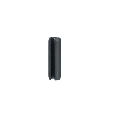
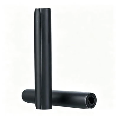
For assemblies that require multiple locating fasteners, PINES can also coordinate the sourcing of matching slotted spring pins and other fasteners. This allows buyers to align dimensional tolerances and surface treatment requirements across related components in the same BOM.
| Standard No. | Pin Type | Material & Hardness | Key Features & Application |
|---|---|---|---|
| DIN 7 | Solid parallel pin (no internal thread) | Carbon steel | Obsolete old DIN standard; multiple tolerances m6/h8/h11; only for spare parts |
| ISO 2338 | Solid parallel pin (no internal thread) | Unhardened steel, austenitic stainless steel | Current European standard, interchangeable with GB/T 119.1‑2000 |
| DIN 6325 | Solid parallel pin (no internal thread) | Quenched steel, 60±2HRC | Legacy dowel pin; JS14 length tolerance; for old‑equipment spare parts only |
| ISO 8734 | Solid parallel pin (no internal thread) | Hardened steel: 550‑650HV30Martensitic SS C1: 460‑560HV30 | Current European standard for precision hardened locating pins, matches GB/T 119.2‑2000 |
| DIN 7979 | With internal removal thread | Carbon steel, quenched steel | Old DIN standard, large size range up to φ80; for maintenance replacement |
| ISO 8735 | With internal removal thread | Hardened steel: 550‑650HV30Martensitic SS C1: 460‑560HV30 | Current European standard for blind‑hole dismountable pins, equivalent to GB/T 120.2‑2000 |
Frequently Asked Questions About Dowel Pin Tolerances
h6 and m6 represent different ISO shaft tolerance zones. For h6, the upper deviation is zero, meaning the maximum shaft diameter corresponds to the nominal size. For m6, the tolerance zone is positioned above the nominal size. Consequently, an m6 shaft will generally have a larger specified dimensional range relative to the nominal size than an h6 shaft in the same diameter range. The appropriate designation depends on the required fit with the mating hole.
Compare the actual pin diameter with the actual hole diameter. When the hole is larger, the difference represents the diametral clearance. For production specifications, engineers should evaluate the maximum and minimum permitted dimensions of both components rather than relying on nominal dimensions alone. This helps determine whether the assembly will consistently achieve the intended fit.
Yes, provided the dimensional relationship meets the assembly requirements. A standard dowel pin can be used with a custom-machined hole if the hole diameter, tolerance, and position are designed to produce the required fit. The engineering team should verify the dimensional limits before production to prevent excessive clearance or interference.
Reaming is used to improve the dimensional accuracy and surface finish of an existing hole. Drilling alone may not consistently achieve the required hole diameter or geometry for precision locating applications. A reaming operation helps bring the finished hole closer to its specified dimensions, although final inspection is still necessary to verify compliance.
Reuse depends on the pin's dimensional condition, surface integrity, and the accuracy required by the assembly. Removal from an interference-fit hole may cause scoring, wear, or other surface damage. The mating hole should also be inspected for deformation. If the pin is used for precision positioning, replacing a damaged or dimensionally altered pin is generally preferable to risking inconsistent assembly results.